
Shunt resistor
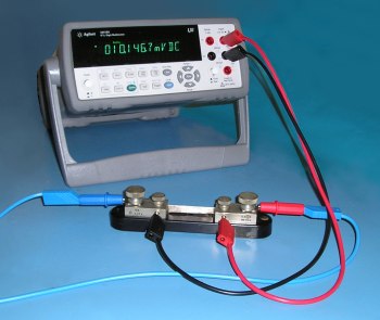
Shunt resistors are often used in cases where currents need to be measured. They can be found in multimeters, as terminating resistors on current transformer or as a separate measurement accessories. When using a combination of an appropriate shunt and an external multimeter set at voltage range, large currents can be measured, or combined with an oscilloscope, current wave forms can be made visible.
The name "shunt" originates from the fact that galvano and moving-iron meters only can handle limited currents. And to be able to measure larger currents a significantly part of the current is bypassed via a resistor. A shunt therefore is a common resistor named after it's purpose.
Calculating shunt resistors

In figure 2 can be seen how a shunt can be placed in parallel to a measuring device. This meter can be a voltmeter or a current meter. A small part of the current I that has to be measured runs through the meter Im and the remaining current Is is diverted through the shunt. Often a high input impedance measuring device is used. In many cases, depending on the value of the shunt resistor and the required accuracy, the current through the measuring instrument can be ignored.
By taking the current to be measured I, the current running through Im and the voltage Vm over the meter, the value of the shunt resistor can be calculated:
 [equ. 1]
The current through the shunt Is is I - Im.
Resistive wire
| Metal | Specific resistance | Resistivity- temperature coefficient | Seebeck coefficient (to copper) |
| · 10-9 Ω·m | · 10-3 K-1 | μV/°C | |
| copper | 16.7...17.5 | 3.9...4.3 | 0 |
| aluminium | 27 | 3.8...4.4 | -3.5 |
| iron | 98 | 6.5 | +10.5 |
| tungsten | 55 | 4.9 | +0.5 |
| silver | 16.1 | 3.9 | -0.5 |
| bronze | 140 | 0.6 | ? |
| chromel A | 113 | 0.1 | +20.5 |
| constantan | 490 | 0.02 | -41.5 |
| manganin | 440 | 0.02 | -1.5 |
| brass | 66 | 2.0 | ? |
| nichrome | 112 | 0.13 | +15.5 |
A shunt resistor is often made of a metal strip or wire. To limit the influence of the temperature a metal with an as small as possible temperature coefficient should be used. An overview of common used metals for shunt resistors with their electrical properties is shown in the table on the left. Constantan and manganin are often used because of their small temperature dependence. Also these materials have a high specific electrical resistivity, so shorter wires are needed.
The required length can be calculated using equation 2. As an example the length of the wire needed for a shunt resistor of 1 Ω which is made from constatan wire with a diameter of 0.5 mm (A = 0.196 mm2).
 [equ. 2]
Temerature depending resistance
The resistance of the shunt wire is not constant, but depends on the temperature of the wire. To which extent the resistance of a material changes with temperature can be found in the column Resistivity temperature coefficient of table 1. The specific resistance in the first column is given at a temperature of 20 °C. The resistance at the new temperature is calculated as:
 [equ. 3],
where RT1 is the shunt resistance at 20 °C, αr is the resistivity temperature coefficient and ΔT is the temperature difference to 20 °C.
If normal copper is used as a resistive element for a 1 Ω shunt and the wire temperature rises to 30 °C (ΔT = 30 °C - 20 °C = 10 °C), the resistance will increase to 17.5·10-9 Ω·m · (1 + 4·10-3 K-1 · 10 °C) = 1.04 Ω. This is a error of 4% at only a temperature rise of 10 °C. It's better to use constantan or manganin. With the same conditions the resistance changes only to 1.0002 Ω.
Thermoelectric voltages
If the voltage drop across the shunt is very small or if the current measurement must be very precise, than thermoelectric voltages could play a role. In most cases the resistive element will be connected to a copper conductor, for example a PCB. This junction of different materials will generate small voltages due to the heating of the shunt by the current. Because there are two junctions (e.g. copper-manganin-copper) with a mirrored configuration, the thermoelectric voltages at both terminals will cancel each other out. But if the heat conductivity of both terminals to the surroundings are unequal, a temperature difference will occur. A temperature difference will also arise when a heat sourse nearby (fuse, semiconductor) heats the terminals unequally. The thermoelectric voltage difference can be calculated as:
 [equ. 4],
where ΔT is the temperature difference between both terminal junctions, αte the Seebeck coefficient against copper as can be found in table 1.
With constantan as the resistive element and a terminal temperature difference of 5 °C the offset voltage will be 5 °C · -41.5 μV = -207.5 μV. This is a quite lage value. In such a case it's better to use manganin which reduces the thermal electric voltage to only -7.5 μV.
Construction

To get the required resistance, specially at higher resistor values and larger currents, the wire length can become quite large. To still get a compact shunt resistor the wire is wound on a form. This introduces parasitic self induction and capacitance that need to be avoided when possible, because a shunt resistor need to be as true ohmic as possible.
The methode of coiling will influence the parasitic characteristics. In the table below shows the results of the self induction measurements of some of the manufacturing methods. In figure 3 the coiling methods are depicted. The different shunts that are measured have similar dimensions.
| Construction | Self induction | Dimensions |
| Coil | 1850 nH | N=11, D=25, l=30 |
| Bifilar | 320 nH | N=11, D=25, l=30 |
| Card | 660 nH | N=13, h=30, w=4, l=30 |
| Ayrton-Perry | 103 nH | N=2*13, h=30, w=4, l=30 |
Of the four measured shunts the coil winding has the largest self inductance. The field of every turn points in the same direction. By bifilar winding, currents trough neighboring turns are in the opposite direction. The fields of two neighboring will eliminate each other out for the most part, which results in a reduced self induction.
Another method to reduce the self induction is making the area that a turn describes smaller by using another winding method such as the card winding. There are shunts available on the market where the wire meanders in a flat surface to keep the described area as small as possible.
The smallest self inductance is measured on the Ayrton-Perry winding. This is in fact a double card winding, made of two windings where the current flows in opposite direction.
The measured shunts have relatively large dimensions and therefore a large self induction compared to measuring shunts that are on the market. Resistors with little self inductance are available with an inductance a few tens of nano Henrys.
Frequency dependence

The parasitic self inductance will increase the impedance at higher frequencies. The extra error added to the tolerance of the resistor due to the measuring frequency can be calculated as follows:
 [equ. 5]
A shunt with an ohmic resistance of 5 Ω and a self induction of 500 nH at a frequency of 1 MHz will have an error of 18,1 %.
Figure 4 shows the freqency dependant impedance of four combinations of ohmic resistances (5 Ω en 100 Ω) and self inductance (50 nH en 500 nH). This clearly shows that at lower ohmic values the self inductance has a greater influence than at higher ohmic values. In general shunts with a lower ohmic value have also smaller parasitic self inductances.
Parasitic self inductance is the biggest problem with shunt resistors. The parasitic capacitance can easily be reduced by adding a wider spacing between neighboring turns. This becomes even more important with multilayer windings.