
Measuring self-inductance & ESR

This article describes some methods to measure the self-inductance and the ESR (equivalent series resistance) of inductors and transformers.
An inductor has as beside its most important property the self-inductance, also parasitic properties. The most important of these are the internal series resistance and the parallel capacitance. The series resistance, also known as the ESR, is mainly determined by the ohmic copper resistance of the windings. The parallel capacitance is formed by the individual isolated windings laying next to each other. A common inductor model with its parasitic components is shown in figure 1.
The measure methods in this article can only determine the self-inductance and ESR. To measure the parasitic capacitance too, a more sophisticated method must be used as described in the article Parasitic properties.
Measure frequency and amplitude
To get usable measuring results, the measure frequency has to be chosen correctly. The designated work frequency of the inductor can be used as a rule. The self-inductance of inductors that include an iron or ferrite core are very dependently on the driving amplitude. If possible, use the the work conditions or lower. Applying a too high drive amplitude will result in measurement errors.
Measuring with a triangle waveform
The first method describes a self-inductance and ESR measurement by using a triangle shaped current.
Measuring arrangement
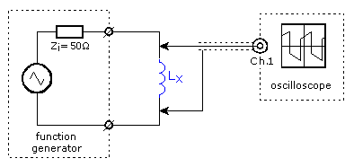
The circuit used for this measurement is shown in figure 2. The inductor to test is connected to a function generator who is outputting a triangle shaped voltage. An oscilloscope is used to measure the voltage across the inductor. The function generator must set at a high as possible output voltage where the inductor doesn't overdrive. The frequency is adjusted so that the voltage across the inductor is kept low as possible but high enough to be measured accurate. In this way the inductor is, as it were connected to a current source.
In this example the voltage setting of the function generator is 5 Vtt (into 50 Ω). Because the output voltage is specified at a load of 50 Ω, The open terminal voltage is the double: 10 Vtt. The top-top current, or current difference is:
![]()

Self-inductance
If voltage is applied to an inductor the current will increase linear in time:
![]() [A]
[A]
The opposite is also true: If an linear in time increasing current flows through an inductor, a constant voltage across the inductor can be observed. And when a triangle shaped current is flowing through an inductor, a squarewave voltage VL can be found across the coil.
Internal series resistance ESR
The oscilloscope screen shot doesn't show a clean square wave, the horizontal line shows an incline. This incline is caused by the voltage across the ohmic portion of the inductor. After all, the voltage across a resistor is proportional to the current. With the amplitude of this incline VR the ESR can be calculated.
Processing measurement data
The voltage belonging to the inductive part is the mean top-voltage VL. The self-inductance is than:
![]()
And the ohmic resistance is:
![]()
Measuring with a sinewave
To measure an inductor with a sinewave voltage, the inductor is added to a halve bridge circuit who is powered by a sinewave generator. The self-induction and ESR is calculated with the measured voltages and phase difference.
The Measurement arrangement

The unknown inductor Lx is connected in series with a current measure resistance Rs and connected to a function generator. The shunt resistor must be kept low but high enough to measure the voltage accurate. With the use of a two channel oscilloscope the voltage across the halve bridge and the the voltage across the inductor as well as the phase difference between these voltages is measured. To measure the internal series resistance accurate, it is important to connect the channel 2 probe as close as possible to the inductor.
The measurement
With the measured values and a mathematical model the self-induction and ESR is calculated as follows.
Mathematical model
Figure 5 shows the mathematical model as used for this calculation and the related vectors can be seen in figure 6. Lx and Rx are the inductive and ohmic components of the inductor. With the use of the resistor Rs the current is measured. This resistor has a low ohmic value to be able to measure the general low ESR of inductors. The load that the probe forms can be neglected. Usually the measure frequency will be low enough that the reactance and the ohmic resistance of the probe doesn't play any role.


Processing measurement data
This example measurement is done on an air coil. The scope screen shot in figure 7 shows the measurement. The measured generator voltage Vg is 1.717 V, the coil voltage Vx 994 mV, the frequency f is 15 kHz and the phase shift α between these two voltages is -39.92 °. The phase has a negative sign, but ignore it in the calculations below. A 10 Ω resistor is used for Rs.

With the measured values the voltage across the resistors Rs and Rx is calculated:

With this the loss angle is calculated as:

The voltage across the ohmic part of the inductor is:
![]()
And from there follows the voltage across the shunt resistor:
![]()
And the current through the circuit is:
![]()
Now the ESR of the coil can be calculated:
![]()
The voltage across the inductive part of the coil is:
![]()
The reactance is:
![]()
And finaly the self-induction is calculated:
![]()
A last remark with this example: There is to be seen that the loss angle φ is about 16 °. The difference between the reactance and ohmic resistance is therefore relative high. In this case the self-inductance can be calculated with a higher accuracy than the internal series resistance. Must the ESR be known with a greater accuracy than the measure frequency must be adjusted to make the loss angle bigger.
Resonance measurement
The self-inductance can also be measured by including it in a resonance circuit. The accuracy of this measurement is directly dependent on the used reference capacitors tolerance. Capacitors with a small tolerance are easily available, but the costs are higher than normal capacitors.
Measuring arrangement

The series circuit of the unknown inductor and the reference capacitor is connected to a sinewave generator as shown in figure 8. Across the so created resonance circuit the voltage is measured with a AC-voltmeter. Most voltmeters aren't suitable to measure very low or high frequencies. As an alternative a dip-meter can also be used. It is possible that the resonance frequency can't be found if the resonance circuit has a high ohmic DC-resistance. In such a case an extra resistor Ra is connected in series with the sinewave generator.
The measurement
To find the resonance frequency the sinewave generator is slowly sweeped though the frequency range whereof the resonance frequency is expected. The resonance frequency is noticeable by the sharp voltage drop read by the volt or dip meter. If the sinewave isn't free of distortion, it is possible that weaker dips in voltage are found on the harmonic frequencies. It is therefore advisable to sweep a larger frequency range and look for the sharpest and deepest voltage drop.
With the found resonance frequency fo and the value of the reference capacitor the self-induction is calculated
![]() [H]
[H]
The internal series resistance can't be determinate with a great accuracy due to the unknown junction resistances.
DC level dependent self-induction
Beside AC-currents also DC-currents are applied to inductors. Examples are choking and filter coils in switched power supplies. The DC-current will cause a certain flux density in the core. The core materials are non-linear and the permeability and therefore the self-induction are dependently of the flux density. The following describes how this DC-current depending self-induction is measured.
Measuring arrangement

The measurement circuit is shown in figure 9. The self-induction measurement is done with a sinewave voltage coming from a function generator. The DC current comes from a DC power supply set to a current limiting mode. To protect the function generator against the DC voltage the signal is fed by a capacitor CG to the inductor under test LX. In order to prevent a high load of the function generator by the power supply, the DC current is supplied via an inductor LV. An exact value for the capacitor CG and inductor LV is of no importance and they don't influence the measurement results. The inductor LV must be suitable for DC currents and may not distort the sinewave. An alternative is a resistor instead of the inductor, but this will generate a lot of heat and a higher DC voltage is needed. The value of the AC current must be kept low as possible but high enough to measure the AC voltage accurate. Further measurement conditions are comparable with a normal sinewave measurement.
Both scope channels must be AC coupled. Instead of the shunt resistor RS a current probe can be used as a better alternative. If a resistor is used first the instantaneous current must be subtracted from the instantaneous voltage to obtain the real voltage.
It is very obvious to connect the power supply and function generator in series to get an AC signal with DC offset. With emphasis: NEVER build a measurement arrangement in this way. The DC current may be very high and will flow through the function generator as well. Function generators are not designed for this kind of currents.
The measurement

This measuring example is done to an off the shelf switched power supply inductor which is specified as 160 µH, 2.5 A. The measure frequency is 10 kHz. As noted earlier, the AC current should be kept low relative to the DC current. In this example the AC current is 12 mA and the DC current stepwise increased from 10 mA to 5 A.
The magnetization must follow for the whole measurement the inital curve. Therefore the core must first be degaussed: Apply the highest AC current possible and decrease the DC current slowly from the maximum current to 0 A, reduce thereafter the AC current slowly. Now the measurement can start: Set the right AC current and increase the DC current in steps, note for each DC current the the AC voltage and current. It is important that within the whole measurement the DC current only increases and corrective decrements must be avoided. This to keep following the initial magnetization curve.
For each DC setting the self-induction is calculated as shown in figure 10. The red trace in the graph shows the results of this measurement. It clear to see how the self-induction highly depends on the DC current. The blue dotted line is from a measurement where the DC setting followed the opposite direction: from high to zero. That the blue line finally reaches the original self-induction is due to the degaussing effects of the AC current.
Accuracy
Overdriving inductor

Especially in inductors with a iron or ferrite core one must be aware that the inductor isn't overdriven. The core materal is non-linear and measure signals will be distorted. The picture in figure 11 shows a overdriven inductor. The green trace represents the voltage across and the magenta one the current through the inductor. For comparison, an undistorted sinewave is laid over both signals to show the distortion more clearly.
Influence cables and instruments
A measurement will always be influenced by the cables and instruments used for the measurement. For a highly accurate measurement these components must be included into the inductor model, whereof the resistances, capacitances and inductances are taking into account. This is of most importance when measuring at high frequencies.
Core losses
The non-linearity of inductors with an iron or ferrite core causes losses that are visible as ohmic losses. These losses are highly frequency dependent.
Parasitic capacitance
The above described measuring methods can't measure the parasitic capacitance of an coil. Therefor a more advanced measurement must be used as described in the article Parasitic properties.