The measurement of magnetic permeability
When designing inductors or transformers it's necessarily to know the magnetic properties of core materials. This article describes how the permeability values of core materials can be determined.
Physical characteristics
Before any measurements can be done, first the physical characteristics like the cross-sectional area Ac and the magnetic path length lc of the core must be known. The article Magnetic Circuits explains this in detail.
Determine the permeability
To measure the permeability the coil must be provided with one coil. The coil must have approximately one turn for every millimeter magnetic path length. The number of turns N must be counted carefully.
Clean the surfaces of dividable cores very carefully. Al the smudge and fluff has to be removed. And the core halves must be clamped straight to each other with a sufficient force.

Connecting diagram
The capacitor isn't most likely necessary. If the function generator outputs a signal that holds a DC voltage, than this can influence the measurement detrimentally. A capacitor is than required. The value isn't very critical but must be large enough to pass the signal without high voltage losses.
The resistor must have a value that is suitable for measuring the current. A value of 10 Ω will do in most cases. The exact value of the resistor R must be known for an accurate measurement.
The measurement
Set the function generator to output a sinewave with a frequency f between 100 and 1000 Hz. Adjust the output voltage to a large as possible amplitude where there isn't any distortion is visible. Optionally adjust the frequency so that both the voltage and current can be read with a high as possible accuracy.
The oscilloscope shows now two signals: the voltage across the inductor VL and the terminal voltage of the function generator Vk, namely the voltage across the resistor and inductor. To obtain the voltage across the resistor VR, these two signals must be subtracted by the oscilloscope, and will results in a third waveform that corresponds to the voltage across the resistorR: vR(t) = vk(t) - vL(t). With the effective resistor voltage the inductor current IL can be determinated:
![]() [A]
[A]
From this the absolute permeability is calculated:
![]() [H-1]
[H-1]
The last step is to calculate the relative permeability: µr = µc / µ0. Where the permeability of vacuum µ0 = 4*π*10-7
Driving dependence permeability
Magnetic materials used for cores in inductors and transformers are non-linear. The permeability is strongly dependable of the field strength. This dependency can be measured and plotted in a graph.

For this measurement the core is magnetized by a variable DC-current. At different field strength values the permeability is measured. To measure the permeability a small AC-current is used to minimize the disturbance of the main field. Choose such an AC field strength that it results in an AC flux density of approximately 10 mT.
The DC-current is derived from an adjustable power supply, and flows via the series resistor Rv and the measurement resistor R through the coil with the test core. Just like the previous measurement the AC-current is delivered by the function generator, and flows via the capacitor C and the measurement resistor R. The capacitor C is now absolutely required! The exact value doesn't matter, as long the voltage drop across the capacitor isn't too large.
Set the input coupling of the oscilloscope to AC. The magnitude of the DC-current can be read from the power supply, or in case if these isn't accurate enough, a current meter should be placed in series with the power supply. The series resistor Rv shouldn't be chosen to small, or else the load on the function generator will be to large.
The number of turns on the test core can be the same as described in the previous measurement. This also applies for the measurement frequency. Increase the DC-current in logarithmic steps to attain a large measurement range with a minimum number of measurements.
Processing measurement data
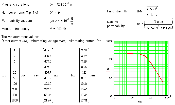
First the core parameters must be defined: cross-sectional area Ac, magnetic path length lc, the number of turns N, and also the frequency f.
For every measure point the DC-current Iac must be set and the AC-voltage Vac and DC-current Iac must be measured and listed. This procedure has to be repeated until the required field strength range is covered. From every measurement the field strength H and the relative permeability μr can be calculated. The series of calculated values can be plotted onto a log-log-graph.

